G-4A - Typical Thrust Block Detail Vertical Crest Anchors G-4B - Typical Thrust Block Detail Vertical Crest Anchors B Values G-5 - Typical Restraint Detail for Slopes Over 20 G-6 - Typical Concrete Encasement G-7 - Typical Pavement Patch for Private Paved Roads G-8 -. Thrust block bend details note 1.

Thrust Block For End Caps Details Dwg Thousands Of Free Autocad Drawings
4INSTALL THRUST BLOCK SO THE.

. WT-01 B Concrete Thrust and Anchor Block Installations - Notes 01-26-2022 Updated. Concrete thrust blocks shall be. 4 REBAR WITH MASTIC COATING WHERE PIPE MUST BE ANCHORED TO THRUST BLOCK.
W 12 12 vertical thrust block details rev0407 thrust restraint concrete thrust block details d -11 d d d 2 min. These details in no way limit the size or location of additional blocking when requested by the county engineer. Thrust block detail drawing stickers decalsartificial fingernailsuv gelmanicure pedicure setnail brushuv lampnail polishView Much more.
Download thousands of free detailed design planning documents including 2D CAD drawings 3D models BIM files and three-part specifications in one place. Contact Lauren Cartwright with any problems or concerns accessing the tool from this site. Section 1 - Mainlaying.
Depend on pressure and pipe size. FY22 Watershed Discount Rate 225 08 for other work in 2021 Normalized Prices for use in FY2021 and earlier years. H1107 H1109 and H1124 to H1131.
Factor of the specific value divided by the standard value. INSTALL AND TEST MAINLINE ACCORDING TO MANUFACTURERS INSTALLATION SPECIFICATIONS. WT-01 A Concrete Thrust and Anchor Block Installations 01-26-2022 Updated.
For bearing areas see detail drawing i-20. Standard Design for Concrete Thrust Blocks. Typical Details of Pipe Trenches.
P 150 DESIGN PRESSURE psi SB 1500 SOIL BEARING PRESSURE psf D 8 PIPE DIAMETER in FS 15 SAFETY FACTOR usually 15 θ 0 DEGREE OF BEND IF APPLICABLE Calculated Data. A thrust block is a concrete pipe restraint that prevents the mainline from moving by transferring pipe loads mainly due to pressure thrust to a wider load-bearing surface. Of Sheets File Size.
Thrust Block Details Concrete Blocks Keywords. Written by Anup Kumar Dey in Civil Pipeline Piping Design Basics Piping Stress Analysis Piping Stress Basics. Horizontal thrust block details w 2 minimum dead end thrust block bend thrust block 2 min.
CONCRETE THRUST BLOCK CALCULATOR Raw Data. Find thrust block dimension for 12 nps 45 bend with 100 psi test pressure. Engineering specifications andor details.
The arrow indicates thrust direction. Shall be wrapped with visqueen or polywrap before concrete is. Standard Drawing Townsville City Council Thrust Block Details Concrete Blocks Created Date.
Standard details thrust block typical horizontal detail no. The tool assesses both the short term and long term expected costs and benefits. Concrete for thrust blocks to be 3000 psi.
Permanent Reinstatement of Pavement Concrete Carriageway Concrete Footway and Run-in Bituminous Pavement Paving SlabBlock Construction - with reference to HyD Standard Drawings Nos. To determine required sizes for different conditions multiply the dimension by a calculations to the engineer for approval of restraint length chosen. Thrust block april 2018.
Usually thrust blocks are provided for buried pipelines at fittings requiring. This drawing represents minimum standards. Dwg section 5 - pipelines thrust blocks 5-1 standard easement widths 120299 5-2 pipe bedding trench backfill for water mains 032511.
Horizontal 14 bend d 1 1 h 25 55 35 w 25 45 35 cy 2 15 dead end tee d 1. Constructed of 420-b-2000 concrete. Drawing 302-2 1998 joint restraint with tie rods notes.
H bend thrust block 2 min. W-1 Typical Trench Detail W-2 Fire Hydrant Assembly W-3A B C D Concrete Thrust Block Detail W-4 Water Service Detail ¾ and 1 Meter W-5 Water Service Detail 1 12 and 2 Meter W-6A B C Air Valve Installation 3 W-7 4 and 6 Blow-Off Assembly W-8 2 and 4 Dead-End Flush-Out W-9 Water Service Detail-3 and Larger Turbine. 101 2011 general information 110-1 2011 plan symbols symbols.
380 1998 thrust blocks for water lines 381 1998 anchor blocks for vertical bends. A The dimensions and design details for concrete thrust blocks for pipe sizes 16-inch and smaller diameter are. Townsville City Council Subject.
All mj and flanged fittings to be wrapped with 12 mil polyethylene prior to placing concrete thrust block 5. Wr-g_th005 and should be reviewed thoroughly. Any modifications to this detail shall first be.
W h dead end thrust block h trench notes. THRUST AND ANCHOR BLOCKS AND PIPE RESTRAINT DETAILS. Thrust Block Detail Drawing.
Section 09000 - standard drawings dwg section 1 - water meters backflow devices 1-1 1 water service 031616 1-1a. REFER TO SPECIFICATIONS FOR TRENCH DEPTHS. Bearing area for thrust blocks shall.
WT-02 Valve Support Blocks 11-16-2007 WT-03A. WT-01C Concrete Thrust and Anchor Block Installations 01-26-2022 Updated. All fittings valves etc.
Depth from ground surface to top of blocking shall be greater than height of blocking 6. Download thousands of free detailed design planning documents including 2D CAD drawings 3D models BIM files and three-part specifications in one place. Bearing Thrust Block Bearing Area ft 2 Safety Factor Thrust Force lbs Bearing Capacity of Undisturbed Soil lbsft2 Undisturbed Soil Bearing Area 45 45 Soil Bearing Strength SB Soil SB lbft2 Muck 0 Soft clay 1000 Silt 1500 Sandy silt 3000 Sand 4000 Sandy clay 6000 Hard clay 9000 Bearing Thrust Block Ht h h 12Ht T A.
Thrust blocks to be used at all lines operating under pressure. Drawing valid only when used as shown and in conjunction with other fairborn issue date. For thrust blocks in existing or proposed roads or road rights of way provide a minimum one and one half 1-12 feet of soil cover unless otherwise directed or approved.
From table 45n bend thrust block dimensioning example. The figure 100 at the thrust block indicates per cent of total thrust to be applied for bearing area. 1 Thrust blocks for pipelines 16-inch and smaller.

Thrust Block Details For Bends Dwg Cad Blocks Free

Typical Thrust Block For Water Mains Dwg Thousands Of Free Autocad Drawings
Typical Thrust Blocking Details Dwg Thousands Of Free Autocad Drawings

Thrust Block For End Caps Details Dwg Thousands Of Free Autocad Drawings

Taper Thrust Block Details Dwg Thousands Of Free Autocad Drawings
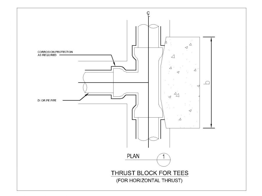
Thrust Block Details For Tees Dwg Thousands Of Free Autocad Drawings

T723 Thrust Blocks

Thrust Blocks
0 comments
Post a Comment